Choose your viewer type
Set your role once and we will tailor the guidance across SIP University.
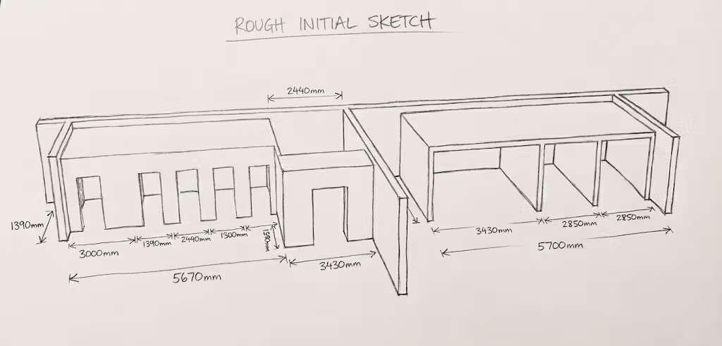
Drawings that prevent delays
Layout drawings are the promise: every line becomes a panel in the factory. Small errors become crane delays and disruption. UltraSIPS uses a repeatable review checklist so errors are caught before manufacturing.
Drawings are the factory instructions, so accuracy protects cost, crane time, and install flow.
What layout drawings are for
Layout drawings are more than a snapshot. They are the bridge between design intent and the physical kit.
Permit and building control review
Drawings are often reviewed for compliance before a kit is released. Make sure your layout set includes the references that building control expects: structural notes, insulation performance, and ventilation intent.
Reading panel numbering
Each panel has a unique ID. The order of IDs often matches the install sequence. Confirm this before delivery so the panels can be staged in order and the install day is smooth.
Isometric views and 3D cues
Isometric views are not decoration. They show how the kit is meant to fit together when floor plans and elevations feel abstract.
SIP design translation
Layouts show how architectural intent becomes a panel pack. Check the grid, confirm offsets, and ensure openings stay on the module.
Load design charts in the drawing set
Layout drawings should reference the span and load tables that informed the panel sizes. This makes the sign-off easier and avoids late engineering changes.
Over-engineering vs right-sizing
Some kits grow because every joint is treated like a heavy load. Use engineering where it adds value, not everywhere.
Roof support structure
Roof structure is often the biggest source of confusion on site. Make sure ridge beams, purlins, and bearing lines are unambiguous in the drawing pack.
Ventilation notes
Airtight shells need planned ventilation. Drawings should show intake and extract locations, service zones, and any back-venting or rainscreen details.
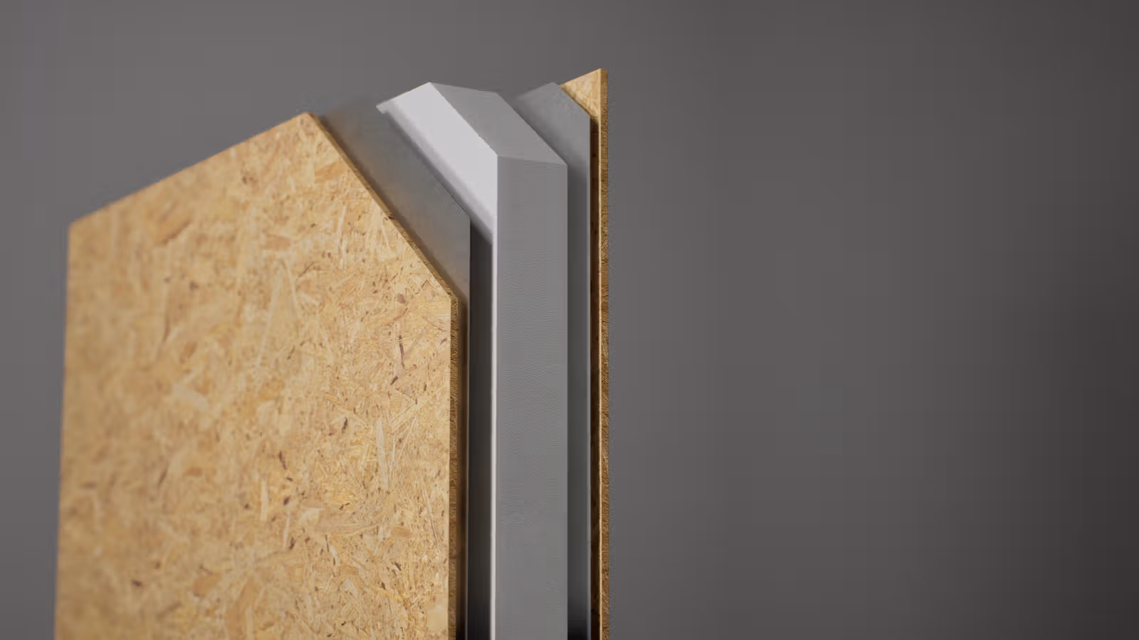
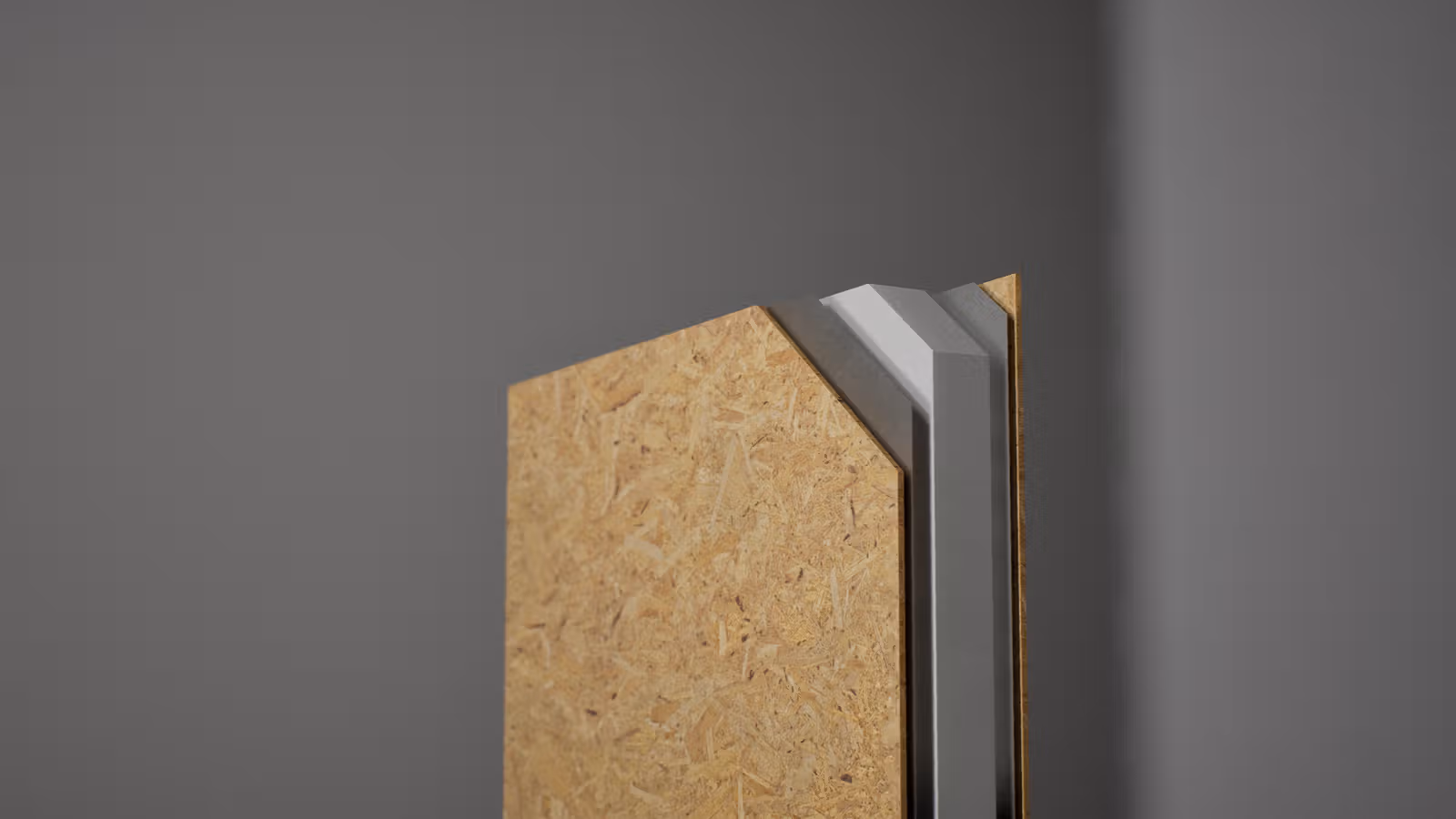
Splines and junctions
The drawing should show what spline is used at each joint. Make sure load-bearing joints get the correct detail and that any thermal breaks are noted.
Revision control
Every layout should include a revision number. Do not build from outdated drawings. Keep a single approved set for site use.
Layout review checklist
- Confirm panel sizes against the architectural plan.
- Verify all openings and structural supports.
- Check spline types at load-bearing joints.
- Confirm roof support lines and bearing points.
- Ensure ventilation notes are present and coordinated.
- Ensure revisions and dates match the final approval.